Mini TX (Basic)
This is the most basic FM transmitter, it is adapted from schematics made by Tetsuo Kogawa, Art Swan, Harry Lythall (SM0VPO) and Practical Electronics, fig 3.94. This design uses an assembly technique called Manhattan Style.
Tools
- Soldering Iron
- Solder
- Tweezers
- 1/4in Bolt
- 2mm Flathead Screwdriver
- Superglue
Components
- Copper PCB
- PCB Squares
- 16AWG Wire (~16in)
- 22AWG Wire (~5in)
- Resistors
- 10k Ohm (1)
- 1k Ohm (1)
- Capacitors
- 0.1uF (1)
- 0.01uF (1)
- 4.7pF (1)
- Trimmer Capacitors
- 0-30pF (1)
- Transistors
- 2N2222 (1)
- Battery Clip
- Audio Cable
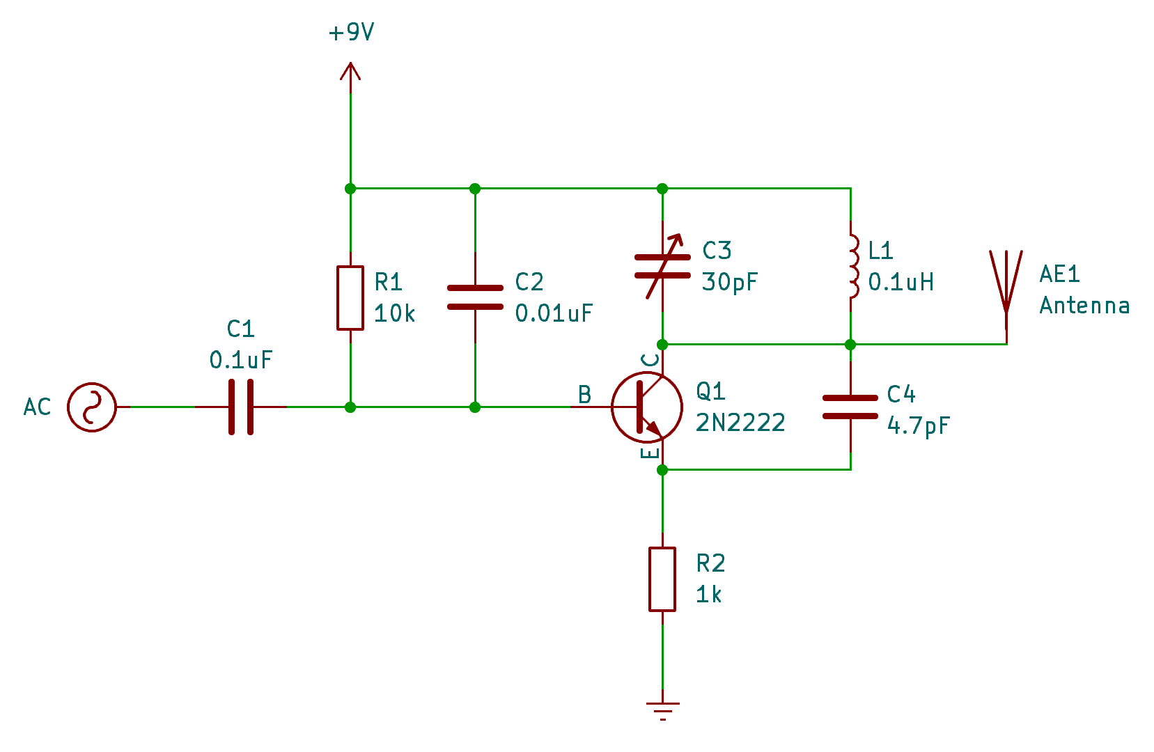
Schematic
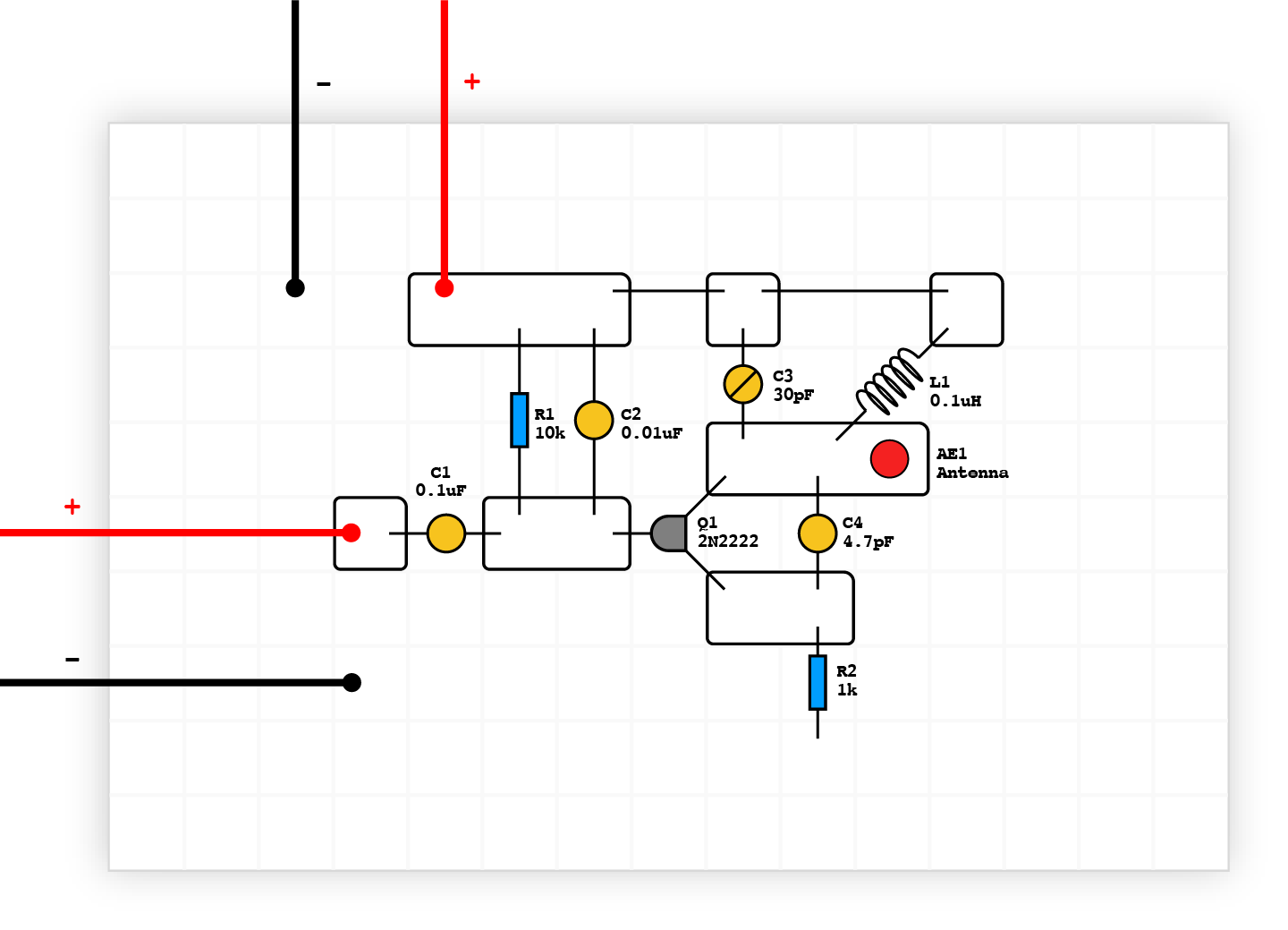
Layout
Instructions
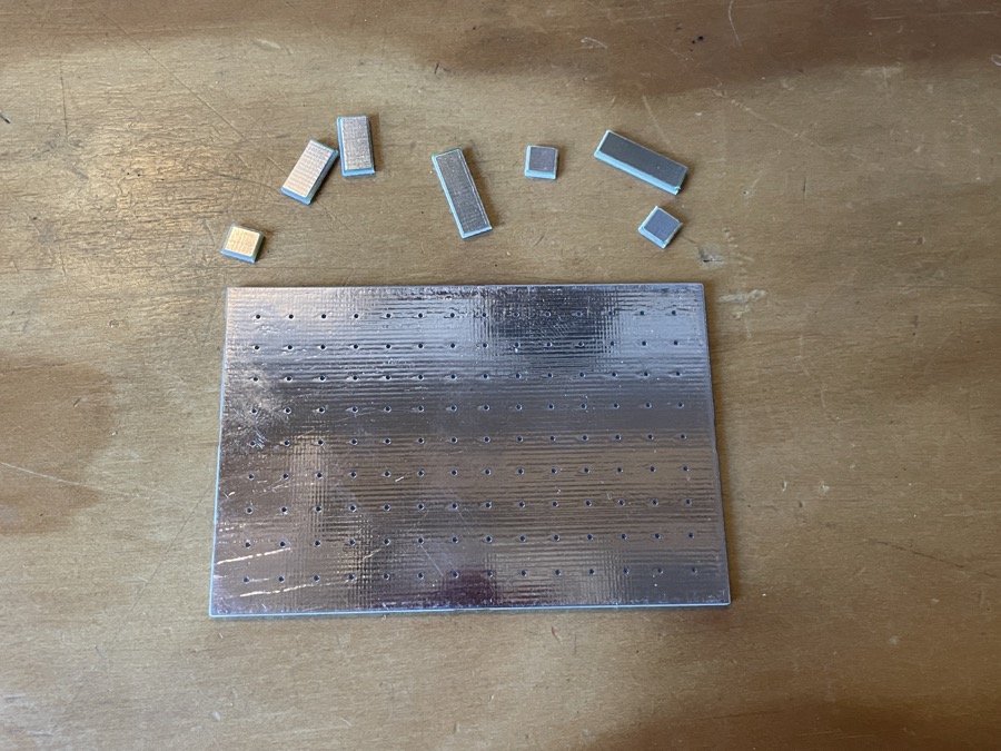
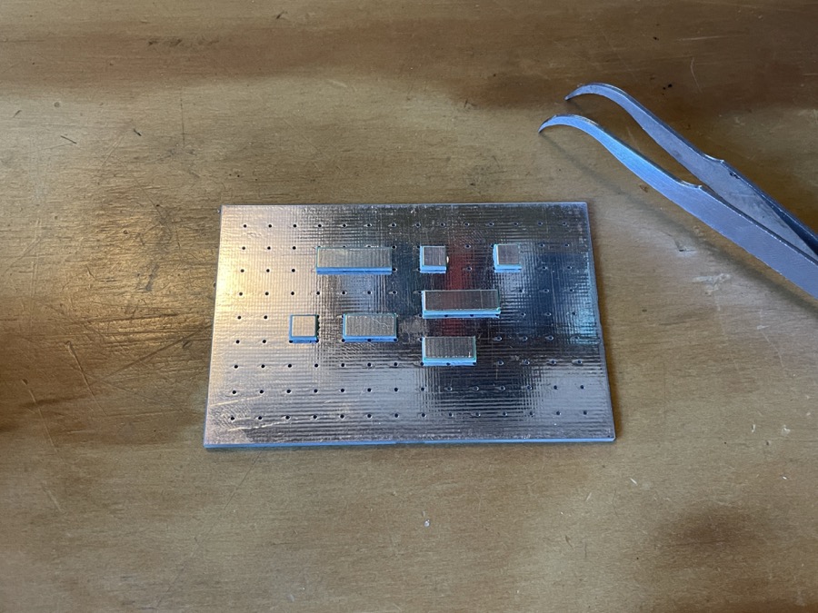
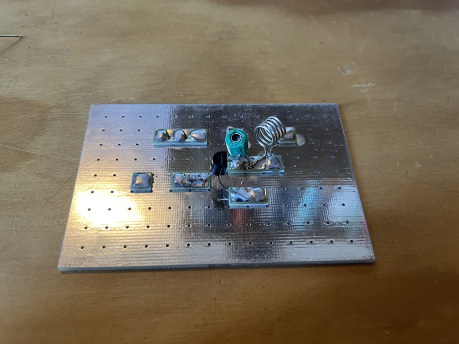
Prep the pcb by gluing the squares according to the given layout:
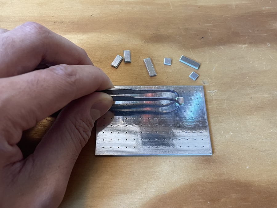
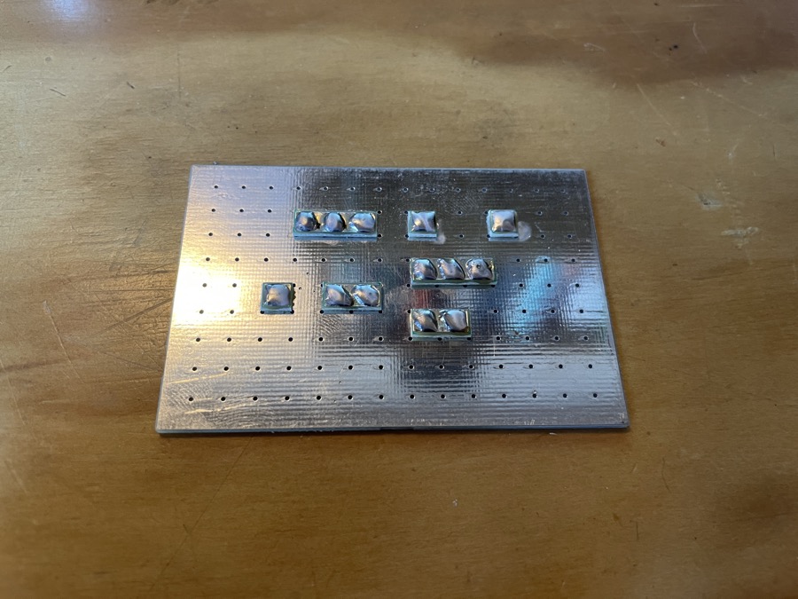
Add solder to the squares, like so:
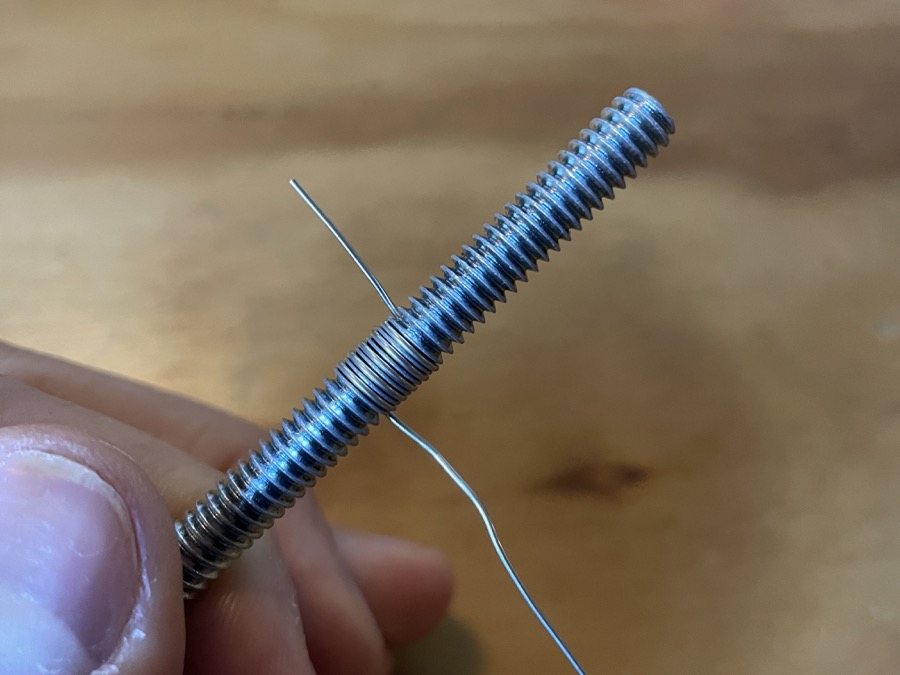
People assemble PCBs in different ways. A popular method is to go from left to right given the schematic. I like to attach the most finicky parts first, so I’ll start with the inductor. Prep the inductor by turning a piece of 22AWG wire around a 1/4in bolt 5 times. This is called an “air coil” and has an inductance of rougly 0.1uH:
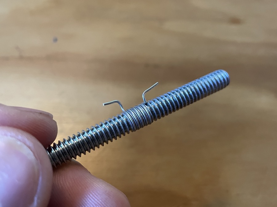
Give it some feet and trim the leads:
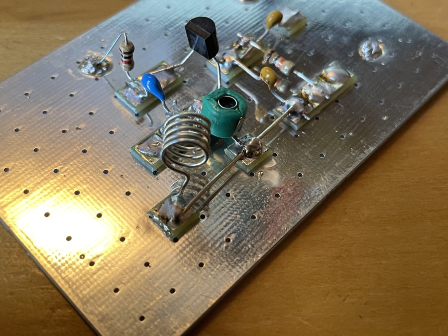
Attach it like so (I also added the transitor and trimmer cap):
Solder all of the parts to the boards, and try to keep the leads or short as possible. Once you’ve attached everything, add some 22AWG between the necessary pads for the power rail:
Attach the battery clip, audio cable, and antenna. This antenna is 16”, which is half of a 1/4 ground plane atenna tuned to 90MHz:
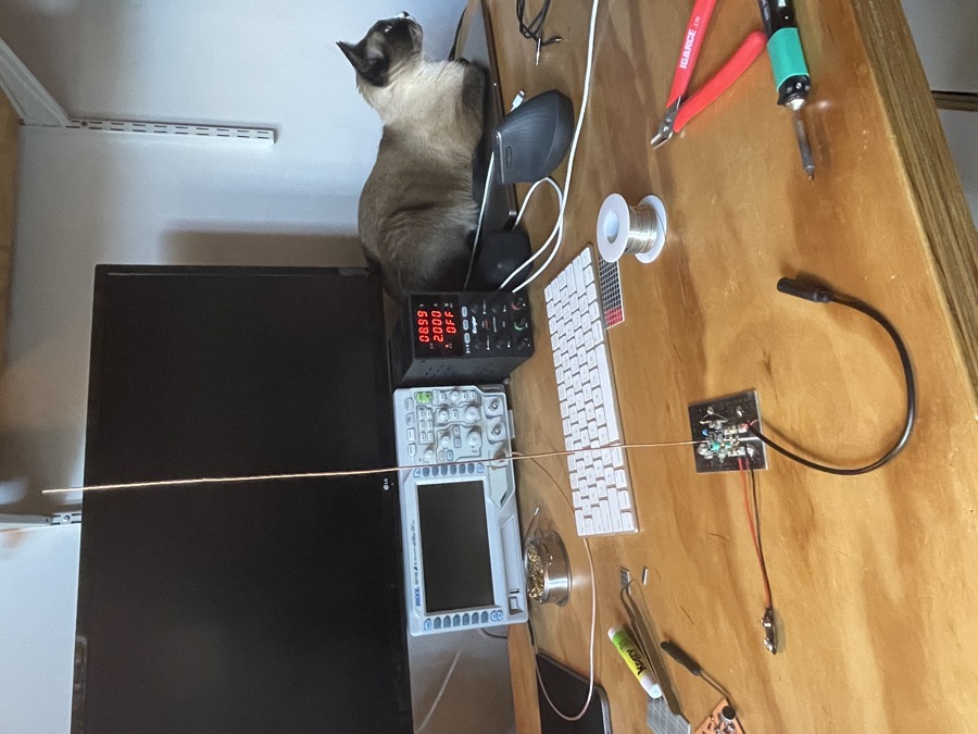
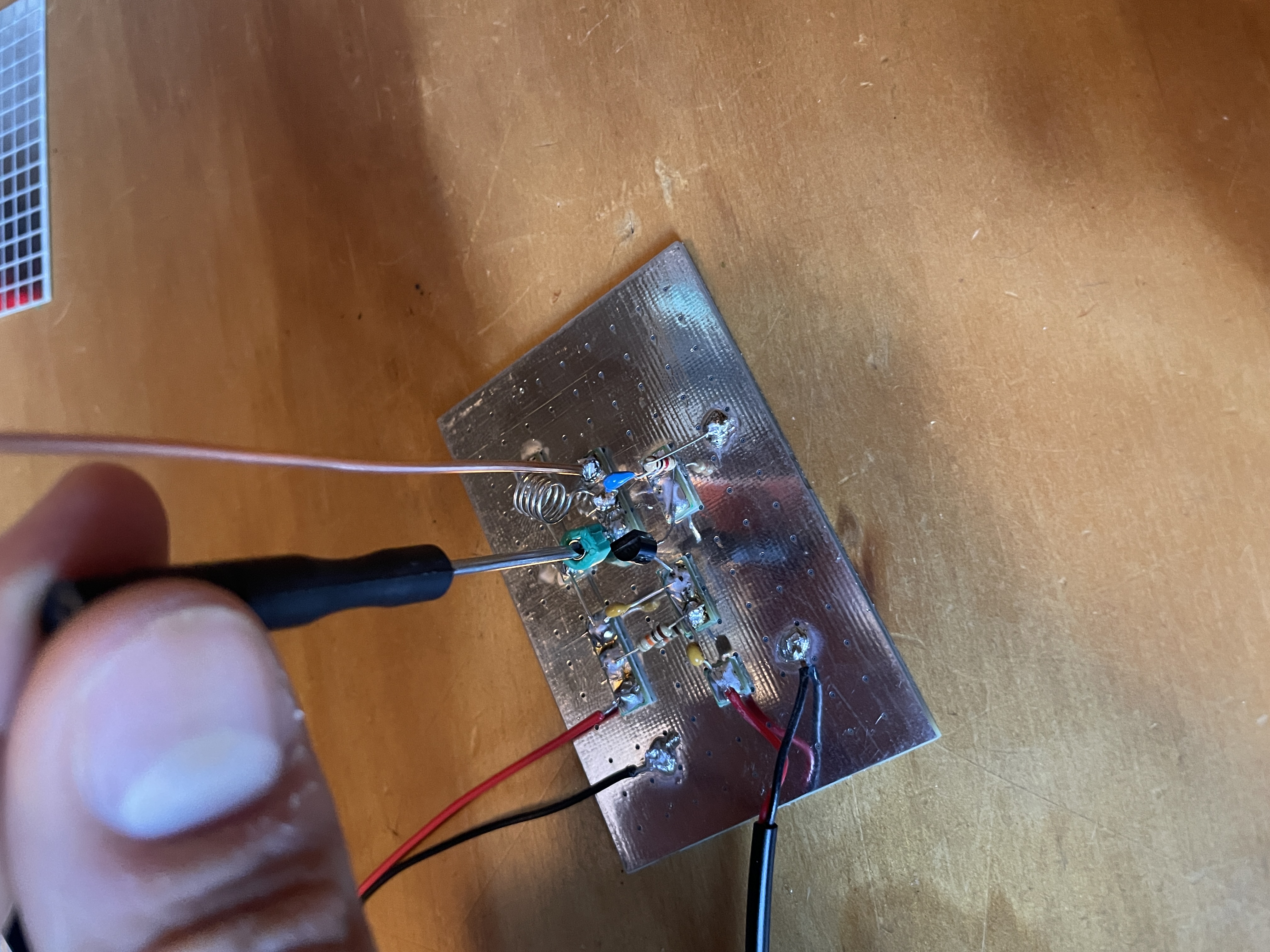
Plug in your battery and audio source. Tune the transmitter using a 2mm screwdriver to the desired frequency. Ideally, you have a frequency counter or oscilloscope. If you dont, you can use an FM reciever find an empty space on the FM spectrum around 88–92MHz. Play a song you recognize, and turn the trimmer capacitor until you can hear it:
Reference
- How to Build a Micro Transmitter
- Art Swan’s Electronic Circuits
- Harry’s Homebrew Homepage
- Manhattan Building Techniques
- Coil Inductance Calculator
- Quarter Wave Antenna Calculator